اس فایل

مرجع دانلود فایل ,تحقیق , پروژه , پایان نامه , فایل فلش گوشی

اس فایل

مرجع دانلود فایل ,تحقیق , پروژه , پایان نامه , فایل فلش گوشی

دانلود کتاب با موضوع خاک ها برای معماری منظر با عنوان Handbook of Soils for landscape architects

اختصاصی از اس فایل دانلود کتاب با موضوع خاک ها برای معماری منظر با عنوان Handbook of Soils for landscape architects دانلود با لینک مستقیم و پر سرعت .

دانلود کتاب با موضوع خاک ها برای معماری منظر با عنوان Handbook of Soils for landscape architects


دانلود کتاب با موضوع خاک ها برای معماری منظر با عنوان Handbook of Soils for landscape architects

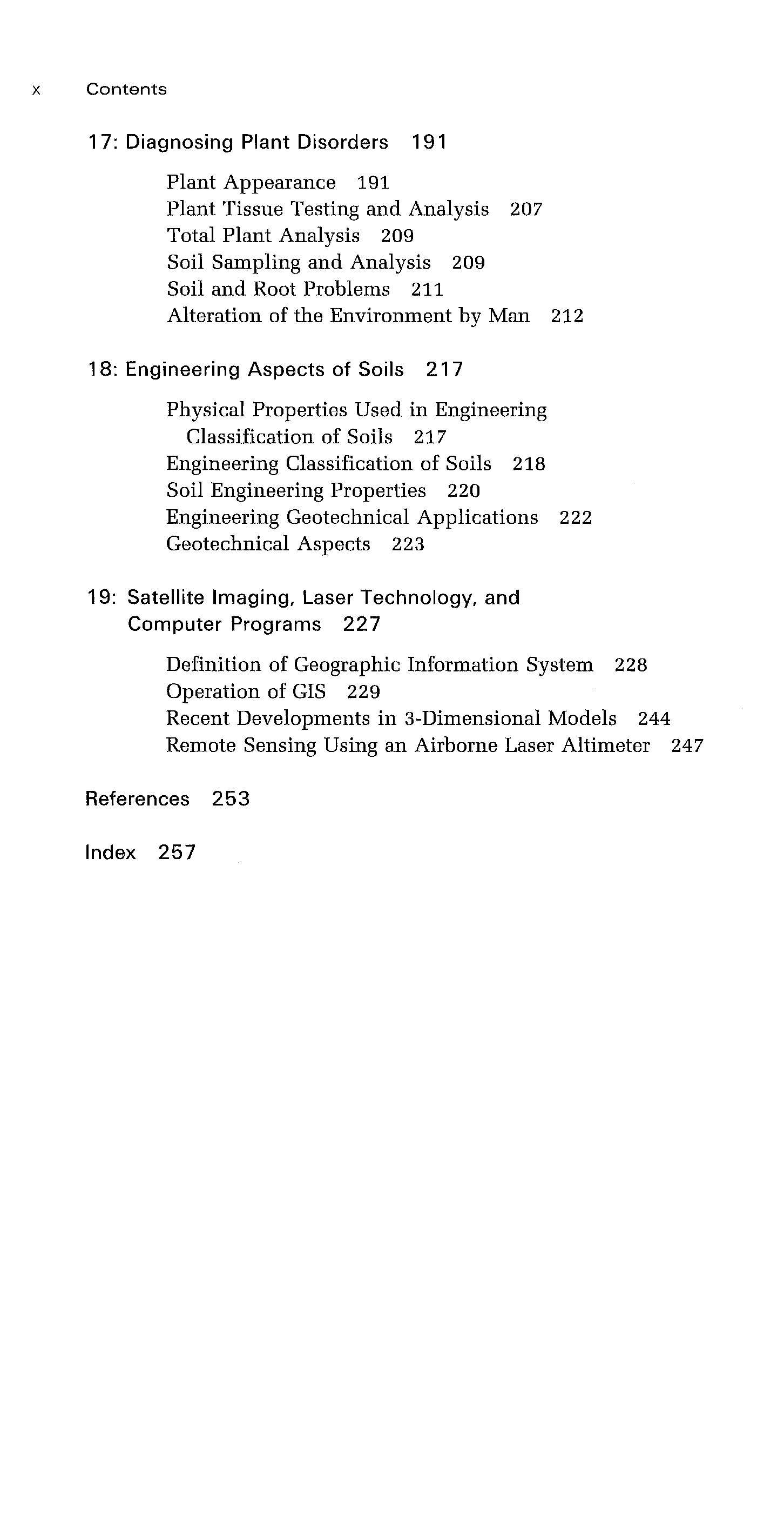
در این بخش  کتاب با موضوع خاک ها برای معماری منظر با عنوان Handbook of Soils for landscape architects  برای دانلود قرار داده شده است. این کتاب  به صورت PDF و در 283 صفحه می‌باشد. در ذیل صفحه معرفی و فهرست مطالب کامل این کتاب آمده است. در صورت تمایل می‌توانید این محصول را از فروشگاه خریداری و دانلود فرمایید.


دانلود با لینک مستقیم


دانلود کتاب با موضوع خاک ها برای معماری منظر با عنوان Handbook of Soils for landscape architects

Stationary Fire Pumps Handbook:2015-NFPA

اختصاصی از اس فایل Stationary Fire Pumps Handbook:2015-NFPA دانلود با لینک مستقیم و پر سرعت .

807 صفحه

Stationary Fire Pumps Handbook:2015-NFPA

ویرایش پنجم

Edited by
Chad R.W. Duffy
Senior Fire Protection Specialist, NFPA


دانلود با لینک مستقیم


Stationary Fire Pumps Handbook:2015-NFPA

Forsthoffer's Rotating Equipment Handbooks

اختصاصی از اس فایل Forsthoffer's Rotating Equipment Handbooks دانلود با لینک مستقیم و پر سرعت .
Forsthoffer's Rotating Equipment Handbooks

Therefore the series objective is to present, in User friendly (easy to
access), practical terms (using familiar analogies), the key facts
concerning rotating equipment design basis, operation, maintenance,
installation and condition monitoring to enable the reader (Engineer,
Operator and Millwright) to:
• Understand the effect of process and environmental changes on
equipment operation, maintenance and reliability
• Condition Monitor equipment on a component basis to optimize
up-time, mean time between failure (MTBF) and mean time to
repair (MTTR)
• Select, audit and test the Equipment that will produce highest safety
and reliability in the field for the lowest life cycle cost.

Table of Contents
1 - Introduction, Pages 1-5
2 - Pump types and applications, Pages 7-24
3 - Pump characteristics—positive displacement vs centrifugal (kinetic), Pages
25-36
4 - Operation of a pump in a process system, Pages 37-42
5 - Pump performance data, Pages 43-52
6 - The concept of pump head, Pages 53-62
7 - Pump selection, Pages 63-84
8 - Centrifugal pump hydraulic disturbances, Pages 85-107
9 - Centrifugal pump testing, Pages 109-122
10 - Pump mechanical design, Pages 123-141
11 -Mechanical seals, Pages 143-159
12 - Pump control and protection, Pages 161-178
13 - Conversion to metric system, Pages 179-190


دانلود با لینک مستقیم


Forsthoffer's Rotating Equipment Handbooks

shaft alignment handbook Third Edition

اختصاصی از اس فایل shaft alignment handbook Third Edition دانلود با لینک مستقیم و پر سرعت .
shaft alignment handbook Third Edition


Table of Contents
Chapter 1
Introduction to Shaft Alignment . . . . . . . . . . . . . . . . . . . . . . . . . . . . . . . . . . . . . . . . . . . . 1
1.1 Benefits of Good Machinery Alignment. . . . . . . . . . . . . . . . . . . . . . . . . . . . . . . . . 1
1.2 Consequences of Defective Alignment . . . . . . . . . . . . . . . . . . . . . . . . . . . . . . . . . . 1
1.2.1 What Happens to Rotating Machinery When It Is Misaligned
a Little Bit, or Moderately, or Even Severely? . . . . . . . . . . . . . . . . . . . . . . . 3
1.3 Four Basic Ingredients Necessary to Insure Alignment Success. . . . . . . . . . . . . . . . 5
1.4 Eight Basic Steps to Align Machinery . . . . . . . . . . . . . . . . . . . . . . . . . . . . . . . . . 15
1.5 How Qualified Are You to Detect and Correct Machinery Misalignment? . . . . . . 19
1.6 Why Should People Be Tested on Their Alignment Skills? . . . . . . . . . . . . . . . . . . 19
1.7 Experience Evaluation for Machinery Alignment . . . . . . . . . . . . . . . . . . . . . . . . . 23
1.8 Who Needs to Be Trained and Qualified in Shaft Alignment? . . . . . . . . . . . . . . . 23
1.9 Assessing a Person’s Knowledge and Experience Level in Shaft Alignment . . . . . . 25
1.10 Alignment Qualification or Certification Testing . . . . . . . . . . . . . . . . . . . . . . . . . 26
1.11 Periodic Alignment Checks . . . . . . . . . . . . . . . . . . . . . . . . . . . . . . . . . . . . . . . . . 31
1.12 Alignment Record Keeping . . . . . . . . . . . . . . . . . . . . . . . . . . . . . . . . . . . . . . . . . 33
References . . . . . . . . . . . . . . . . . . . . . . . . . . . . . . . . . . . . . . . . . . . . . . . . . . . . . . . . . . 33
Chapter 2
Detecting Misalignment on Rotating Machinery . . . . . . . . . . . . . . . . . . . . . . . . . . . . . . . 35
2.1 The Four Maintenance Philosophies . . . . . . . . . . . . . . . . . . . . . . . . . . . . . . . . . . . 35
2.1.1 Breakdown or Run-to-Failure Maintenance . . . . . . . . . . . . . . . . . . . . . . . 35
2.1.2 Preventive or Time-Based Maintenance . . . . . . . . . . . . . . . . . . . . . . . . . . 36
2.1.3 Predictive or Condition-Based Maintenance . . . . . . . . . . . . . . . . . . . . . . . 36
2.1.4 Proactive or Prevention Maintenance . . . . . . . . . . . . . . . . . . . . . . . . . . . . 37
2.1.5 Industrial Maintenance Philosophy Survey Results . . . . . . . . . . . . . . . . . . 37
2.2 Types of Forces That Occur on Rotating Machinery . . . . . . . . . . . . . . . . . . . . . . . 37
2.2.1 How Mass, Stiffness, and Damping Affect the Vibration Response
of Machinery . . . . . . . . . . . . . . . . . . . . . . . . . . . . . . . . . . . . . . . . . . . . . . 39
2.2.2 How Vibration Is Measured . . . . . . . . . . . . . . . . . . . . . . . . . . . . . . . . . . . 40
2.2.3 Time and Frequency Domain Vibration Information . . . . . . . . . . . . . . . . 44
2.2.4 Using Vibration Analysis to Detect Misalignment. . . . . . . . . . . . . . . . . . . 46
2.2.5 Relationship between Vibration Amplitude and Misalignment Severity . . . 48
2.2.6 Vibration Results from a Controlled Misalignment Test
on a Training Demonstrator. . . . . . . . . . . . . . . . . . . . . . . . . . . . . . . . . . . 49
2.2.7 Vibration Results from a Controlled Misalignment Test on a Motor and
Pump. . . . . . . . . . . . . . . . . . . . . . . . . . . . . . . . . . . . . . . . . . . . . . . . . . . . 52
2.2.8 Before and after Vibration Results Found on a Misaligned
Motor and Pump. . . . . . . . . . . . . . . . . . . . . . . . . . . . . . . . . . . . . . . . . . . 63
2.2.9 Why Vibration Levels Often Decrease with Increasing Misalignment. . . . . 66
2.2.10 Known Vibration Spectral Signatures of Misaligned
Flexible Couplings . . . . . . . . . . . . . . . . . . . . . . . . . . . . . . . . . . . . . . . . . . 71
2.2.11 Vibration Characteristics of Misaligned Machinery Supported
in Sliding Type Bearings. . . . . . . . . . . . . . . . . . . . . . . . . . . . . . . . . . . . . . 71
2.2.12 Using Infrared Thermography to Detect Misalignment . . . . . . . . . . . . . . . 71
2.2.13 Power Loss due to Shaft Misalignment. . . . . . . . . . . . . . . . . . . . . . . . . . . 78
2.2.14 The Most Effective Way to Determine if Misalignment Exists . . . . . . . . . . 78
Bibliography . . . . . . . . . . . . . . . . . . . . . . . . . . . . . . . . . . . . . . . . . . . . . . . . . . . . . . . . . 86
Chapter 3
Foundations, Baseplates, Installation, and Piping Strain. . . . . . . . . . . . . . . . . . . . . . . . . . 89
3.1 Varying Composition of Earth’s Surface Layer . . . . . . . . . . . . . . . . . . . . . . . . . . . 90
3.2 How Do We Hold This Equipment in Place? . . . . . . . . . . . . . . . . . . . . . . . . . . . . . 90
3.2.1 Baseplates . . . . . . . . . . . . . . . . . . . . . . . . . . . . . . . . . . . . . . . . . . . . . . . . 92
3.2.1.1 Advantages . . . . . . . . . . . . . . . . . . . . . . . . . . . . . . . . . . . . . . . 92
3.2.1.2 Disadvantages . . . . . . . . . . . . . . . . . . . . . . . . . . . . . . . . . . . . . 94
3.2.2 Soleplates. . . . . . . . . . . . . . . . . . . . . . . . . . . . . . . . . . . . . . . . . . . . . . . . . 94
3.2.2.1 Advantages . . . . . . . . . . . . . . . . . . . . . . . . . . . . . . . . . . . . . . . 95
3.2.2.2 Disadvantages . . . . . . . . . . . . . . . . . . . . . . . . . . . . . . . . . . . . . 95
3.2.3 Frames . . . . . . . . . . . . . . . . . . . . . . . . . . . . . . . . . . . . . . . . . . . . . . . . . . 95
3.2.3.1 Advantages . . . . . . . . . . . . . . . . . . . . . . . . . . . . . . . . . . . . . . . 96
3.2.3.2 Disadvantages . . . . . . . . . . . . . . . . . . . . . . . . . . . . . . . . . . . . . 96
3.2.4 Monolithic Rigid Foundations . . . . . . . . . . . . . . . . . . . . . . . . . . . . . . . . . 97
3.2.4.1 Advantages . . . . . . . . . . . . . . . . . . . . . . . . . . . . . . . . . . . . . . . 98
3.2.4.2 Disadvantages . . . . . . . . . . . . . . . . . . . . . . . . . . . . . . . . . . . . . 98
3.2.4.3 Tips for Designing Good Foundations . . . . . . . . . . . . . . . . . . . 98
3.2.4.4 Tips on Installing Foundations and Rotating
Machinery . . . . . . . . . . . . . . . . . . . . . . . . . . . . . . . . . . . . . . . . 99
3.2.5 Baseplates Attached to Concrete Floors . . . . . . . . . . . . . . . . . . . . . . . . . 100
3.2.5.1 Advantages . . . . . . . . . . . . . . . . . . . . . . . . . . . . . . . . . . . . . . 101
3.2.5.2 Disadvantages . . . . . . . . . . . . . . . . . . . . . . . . . . . . . . . . . . . . 101
3.2.6 Anchor Bolts . . . . . . . . . . . . . . . . . . . . . . . . . . . . . . . . . . . . . . . . . . . . . 102
3.2.7 Inertia Blocks. . . . . . . . . . . . . . . . . . . . . . . . . . . . . . . . . . . . . . . . . . . . . 103
3.2.7.1 Advantages . . . . . . . . . . . . . . . . . . . . . . . . . . . . . . . . . . . . . . 103
3.2.7.2 Disadvantages . . . . . . . . . . . . . . . . . . . . . . . . . . . . . . . . . . . . 103
3.2.8 Cement, Concrete, and Grout Basics . . . . . . . . . . . . . . . . . . . . . . . . . . . 104
3.2.9 Reinforced Concrete. . . . . . . . . . . . . . . . . . . . . . . . . . . . . . . . . . . . . . . . 105
3.2.10 Grouting . . . . . . . . . . . . . . . . . . . . . . . . . . . . . . . . . . . . . . . . . . . . . . . . 105
3.2.10.1 Traditional Grouting Methods . . . . . . . . . . . . . . . . . . . . . . . . 105
3.2.10.2 Suggested Grouting Procedure . . . . . . . . . . . . . . . . . . . . . . . . 108
3.2.11 Pregrouted and Solid Metal Baseplates . . . . . . . . . . . . . . . . . . . . . . . . . . 109
3.2.12 Case History of Installing a Baseplate Using Epoxy-Based
Grout . . . . . . . . . . . . . . . . . . . . . . . . . . . . . . . . . . . . . . . . . . . . . . . . . . 111
3.3 Problems to Look for in Your Foundations and Baseplates . . . . . . . . . . . . . . . . . 129
3.3.1 Piping, Ductwork, and Conduit Strain . . . . . . . . . . . . . . . . . . . . . . . . . . 131
3.4 Checking for Excessive Static Piping Forces on
Rotating Equipment . . . . . . . . . . . . . . . . . . . . . . . . . . . . . . . . . . . . . . . . . . . . . . 134
3.5 Visual Inspection Checklist . . . . . . . . . . . . . . . . . . . . . . . . . . . . . . . . . . . . . . . . . 134
3.6 How Long Will Rotating Machinery Stayed Accurately Aligned?. . . . . . . . . . . . . 135
References . . . . . . . . . . . . . . . . . . . . . . . . . . . . . . . . . . . . . . . . . . . . . . . . . . . . . . . . . 136
Chapter 4
Flexible and Rigid Couplings . . . . . . . . . . . . . . . . . . . . . . . . . . . . . . . . . . . . . . . . . . . . 137
4.1 Coupling and Shaft Misalignment Tolerances—What Is the Difference?. . . . . . . . 137
4.2 The Role of the Flexible Coupling. . . . . . . . . . . . . . . . . . . . . . . . . . . . . . . . . . . . 138
4.3 What to Consider When Specifying a Flexible Coupling . . . . . . . . . . . . . . . . . . . 138
4.4 Types of Flexible Couplings . . . . . . . . . . . . . . . . . . . . . . . . . . . . . . . . . . . . . . . . 139
4.4.1 Mechanically Flexible Coupling Designs. . . . . . . . . . . . . . . . . . . . . . . . . . 141
4.4.1.1 Chain Couplings . . . . . . . . . . . . . . . . . . . . . . . . . . . . . . . . . . . . 141
4.4.1.2 Gear Couplings . . . . . . . . . . . . . . . . . . . . . . . . . . . . . . . . . . . . . 141
4.4.1.3 Metal Ribbon Couplings . . . . . . . . . . . . . . . . . . . . . . . . . . . . . . 151
4.4.1.4 Universal Joint Couplings . . . . . . . . . . . . . . . . . . . . . . . . . . . . . 152
4.4.1.5 Flexible Link. . . . . . . . . . . . . . . . . . . . . . . . . . . . . . . . . . . . . . . 153
4.4.1.6 Leaf Spring . . . . . . . . . . . . . . . . . . . . . . . . . . . . . . . . . . . . . . . . 155
4.4.1.7 Pin Drive. . . . . . . . . . . . . . . . . . . . . . . . . . . . . . . . . . . . . . . . . . 156
4.4.1.8 Elastomeric Couplings . . . . . . . . . . . . . . . . . . . . . . . . . . . . . . . . 156
4.4.2 Metallic Membrane=Disk-Type Coupling Designs . . . . . . . . . . . . . . . . . . 159
4.4.2.1 Diaphragm Couplings . . . . . . . . . . . . . . . . . . . . . . . . . . . . . . . . 159
4.4.2.2 Flexible Disc Couplings . . . . . . . . . . . . . . . . . . . . . . . . . . . . . . . 161
4.5 Rigid Coupling Design . . . . . . . . . . . . . . . . . . . . . . . . . . . . . . . . . . . . . . . . . . . . 162
4.6 Flexible Coupling Lubrication. . . . . . . . . . . . . . . . . . . . . . . . . . . . . . . . . . . . . . . 162
4.7 Coupling Installation . . . . . . . . . . . . . . . . . . . . . . . . . . . . . . . . . . . . . . . . . . . . . 163
4.8 Coupling Hub Attachment Methods . . . . . . . . . . . . . . . . . . . . . . . . . . . . . . . . . . 164
4.9 Keys and Keyways . . . . . . . . . . . . . . . . . . . . . . . . . . . . . . . . . . . . . . . . . . . . . . . 165
4.9.1 Types of Keys . . . . . . . . . . . . . . . . . . . . . . . . . . . . . . . . . . . . . . . . . . . . . 166
4.9.2 Straight Bore—Sliding Clearance with Keyways . . . . . . . . . . . . . . . . . . . . 168
4.9.3 Straight Bore—Interference Fit with Keyways . . . . . . . . . . . . . . . . . . . . . 168
4.9.4 Splined Shaft with End Lock Nut or Locking Plate . . . . . . . . . . . . . . . . . 170
4.9.5 Tapered Bore—Interference Fit with Keyways . . . . . . . . . . . . . . . . . . . . . 170
4.9.6 Coupling Hub to Shaft Surface Contact . . . . . . . . . . . . . . . . . . . . . . . . . . 171
4.9.7 Keyless Taper Bores. . . . . . . . . . . . . . . . . . . . . . . . . . . . . . . . . . . . . . . . . 172
4.9.8 Proper Interference Fit for Hydraulically Installed Coupling Hubs . . . . . . 172
4.9.9 Installation of Keyless Coupling Hubs Using Hydraulic Expansion. . . . . . 173
Bibliography . . . . . . . . . . . . . . . . . . . . . . . . . . . . . . . . . . . . . . . . . . . . . . . . . . . . . . . . 175
Chapter 5
Preliminary Alignment Checks . . . . . . . . . . . . . . . . . . . . . . . . . . . . . . . . . . . . . . . . . . . 179
5.1 Foundation and Base Plate Checks . . . . . . . . . . . . . . . . . . . . . . . . . . . . . . . . . . . 179
5.2 Dial Indicator Basics. . . . . . . . . . . . . . . . . . . . . . . . . . . . . . . . . . . . . . . . . . . . . . 180
5.3 Damaged, Worn, or Improperly Installed Machinery Component Checks . . . . . . 180
5.4 Runout. . . . . . . . . . . . . . . . . . . . . . . . . . . . . . . . . . . . . . . . . . . . . . . . . . . . . . . . 194
5.5 Machine Housing to Base Plate Interface Problems . . . . . . . . . . . . . . . . . . . . . . . 202
5.6 Verifying That the Soft Foot Has Been Eliminated . . . . . . . . . . . . . . . . . . . . . . . 205
5.6.1 Multiple Bolt–Multiple Indicator Method (Preferred Method) . . . . . . . . . 205
5.6.2 Multiple Bolt–Single Indicator Method (Second Choice). . . . . . . . . . . . . . 207
5.6.3 Shaft Movement Method (Third Choice) . . . . . . . . . . . . . . . . . . . . . . . . . 212
5.6.4 Single Bolt–Single Indicator Method (Last Choice). . . . . . . . . . . . . . . . . . 212
5.7 Other Methods for Correcting Soft Foot Problems . . . . . . . . . . . . . . . . . . . . . . . 214
Chapter 6
Shaft Alignment Measuring Tools . . . . . . . . . . . . . . . . . . . . . . . . . . . . . . . . . . . . . . . . 219
6.1 Dimensional Measurement . . . . . . . . . . . . . . . . . . . . . . . . . . . . . . . . . . . . . . . . 220
6.2 Classes of Dimensional Measurement Tools and Sensors . . . . . . . . . . . . . . . . . . 220
6.2.1 Standard Tape Measures, Rulers, and Straightedges . . . . . . . . . . . . . . . 221
6.2.2 Feeler and Taper Gauges . . . . . . . . . . . . . . . . . . . . . . . . . . . . . . . . . . . 221
6.2.3 Slide Caliper . . . . . . . . . . . . . . . . . . . . . . . . . . . . . . . . . . . . . . . . . . . . . 223
6.2.4 Micrometers . . . . . . . . . . . . . . . . . . . . . . . . . . . . . . . . . . . . . . . . . . . . . 223
6.2.5 Dial Indicators . . . . . . . . . . . . . . . . . . . . . . . . . . . . . . . . . . . . . . . . . . . 225
6.2.6 Optical Alignment Tooling . . . . . . . . . . . . . . . . . . . . . . . . . . . . . . . . . . 226
6.2.7 Optical Parallax . . . . . . . . . . . . . . . . . . . . . . . . . . . . . . . . . . . . . . . . . . 229
6.2.8 Proximity Probes . . . . . . . . . . . . . . . . . . . . . . . . . . . . . . . . . . . . . . . . . 232
6.2.9 Linear Variable Differential Transformers. . . . . . . . . . . . . . . . . . . . . . . 233
6.2.10 Optical Encoders . . . . . . . . . . . . . . . . . . . . . . . . . . . . . . . . . . . . . . . . . 235
6.2.11 Lasers and Detectors . . . . . . . . . . . . . . . . . . . . . . . . . . . . . . . . . . . . . . 235
6.2.12 Charge Couple Devices . . . . . . . . . . . . . . . . . . . . . . . . . . . . . . . . . . . . . 241
6.2.13 Interferometers . . . . . . . . . . . . . . . . . . . . . . . . . . . . . . . . . . . . . . . . . . . 243
6.3 Sweeping 908 Arcs Twice to Measure a Misalignment Condition . . . . . . . . . . . . 245
6.4 Why Measurements Are Taken at 908 Intervals . . . . . . . . . . . . . . . . . . . . . . . . . 249
6.5 Rotating Both Shafts to Override a Runout Condition. . . . . . . . . . . . . . . . . . . . 249
6.6 Tips for Getting Good Alignment Measurements. . . . . . . . . . . . . . . . . . . . . . . . 251
6.7 Engaged Couplings Will Produce Measurement Errors . . . . . . . . . . . . . . . . . . . 252
6.8 Rim Indicator Setup Variations . . . . . . . . . . . . . . . . . . . . . . . . . . . . . . . . . . . . . 253
6.9 Rim Readings Indicate Twice the Centerline Offset . . . . . . . . . . . . . . . . . . . . . . 253
6.10 Validity Rule. . . . . . . . . . . . . . . . . . . . . . . . . . . . . . . . . . . . . . . . . . . . . . . . . . . 253
6.11 Partial Arc Mathematics . . . . . . . . . . . . . . . . . . . . . . . . . . . . . . . . . . . . . . . . . . 255
6.11.1 Partial Arc Measurement Procedure . . . . . . . . . . . . . . . . . . . . . . . . . . . 260
6.11.2 Partial Arc Measurement Sample Problem . . . . . . . . . . . . . . . . . . . . . . 262
6.11.3 Pitfalls of Partial Arc Measurements . . . . . . . . . . . . . . . . . . . . . . . . . . . 266
6.12 Bracket or Bar Sag . . . . . . . . . . . . . . . . . . . . . . . . . . . . . . . . . . . . . . . . . . . . . . 267
6.13 Xmas Tree Brackets and Face Sag. . . . . . . . . . . . . . . . . . . . . . . . . . . . . . . . . . . 269
6.14 Zero Sag Brackets . . . . . . . . . . . . . . . . . . . . . . . . . . . . . . . . . . . . . . . . . . . . . . . 271
6.15 Dial Indicator Shaft Alignment System Manufacturers . . . . . . . . . . . . . . . . . . . 272
6.15.1 Accushim Systems . . . . . . . . . . . . . . . . . . . . . . . . . . . . . . . . . . . . . . . . 273
6.15.2 A-Line Systems. . . . . . . . . . . . . . . . . . . . . . . . . . . . . . . . . . . . . . . . . . . 274
6.15.3 Benchmark System . . . . . . . . . . . . . . . . . . . . . . . . . . . . . . . . . . . . . . . . 276
6.15.4 Murray & Garig System . . . . . . . . . . . . . . . . . . . . . . . . . . . . . . . . . . . . 276
6.15.5 Peterson Alignment Tools Co. Systems . . . . . . . . . . . . . . . . . . . . . . . . . 277
6.15.6 Turvac Inc. Systems . . . . . . . . . . . . . . . . . . . . . . . . . . . . . . . . . . . . . . . 279
6.15.7 Update International System. . . . . . . . . . . . . . . . . . . . . . . . . . . . . . . . . 282
6.16 Dial Indicator Manufacturers Hardware Specifications . . . . . . . . . . . . . . . . . . . 282
Bibliography . . . . . . . . . . . . . . . . . . . . . . . . . . . . . . . . . . . . . . . . . . . . . . . . . . . . . . . . 288
Chapter 7
Correcting Misalignment . . . . . . . . . . . . . . . . . . . . . . . . . . . . . . . . . . . . . . . . . . . . . . . 291
7.1 Installing Machinery for the First Time . . . . . . . . . . . . . . . . . . . . . . . . . . . . . . . . 291
7.2 Bolt-Bound Conditions . . . . . . . . . . . . . . . . . . . . . . . . . . . . . . . . . . . . . . . . . . . . 292
7.3 Last Resort Measures for Bolt-Bound Conditions . . . . . . . . . . . . . . . . . . . . . . . . 294
7.4 Machinery Positioning Basics . . . . . . . . . . . . . . . . . . . . . . . . . . . . . . . . . . . . . . . 296
7.4.1 Axial Spacing . . . . . . . . . . . . . . . . . . . . . . . . . . . . . . . . . . . . . . . . . . . . . 296
7.4.2 Making Corrections in the Vertical Direction . . . . . . . . . . . . . . . . . . . . . . 298
7.4.3 Lateral Movement . . . . . . . . . . . . . . . . . . . . . . . . . . . . . . . . . . . . . . . . . . 301
7.4.4 Vertical Movement . . . . . . . . . . . . . . . . . . . . . . . . . . . . . . . . . . . . . . . . . 304
7.5 Types of Movement Tools. . . . . . . . . . . . . . . . . . . . . . . . . . . . . . . . . . . . . . . . . . 304
7.5.1 Pry and Crowbars and Wedges . . . . . . . . . . . . . . . . . . . . . . . . . . . . . . . . 305
7.5.2 Comealongs and Chain Falls . . . . . . . . . . . . . . . . . . . . . . . . . . . . . . . . . . 306
7.5.3 Hydraulic Jacks . . . . . . . . . . . . . . . . . . . . . . . . . . . . . . . . . . . . . . . . . . . . 306
7.5.4 Permanent Jackscrews . . . . . . . . . . . . . . . . . . . . . . . . . . . . . . . . . . . . . . . 307
7.5.5 Portable Jackscrews and Machinery Positioners . . . . . . . . . . . . . . . . . . . . 307
7.6 What to Do When Things Are Not Working. . . . . . . . . . . . . . . . . . . . . . . . . . . . 307
7.7 Misalignment Rantings . . . . . . . . . . . . . . . . . . . . . . . . . . . . . . . . . . . . . . . . . . . . 315
Bibliography . . . . . . . . . . . . . . . . . . . . . . . . . . . . . . . . . . . . . . . . . . . . . . . . . . . . . . . . 317
Chapter 8
Alignment Modeling Basics . . . . . . . . . . . . . . . . . . . . . . . . . . . . . . . . . . . . . . . . . . . . . 319
8.1 Graphing and Modeling Alignment Techniques . . . . . . . . . . . . . . . . . . . . . . . . . . 321
8.2 Basic Alignment Models . . . . . . . . . . . . . . . . . . . . . . . . . . . . . . . . . . . . . . . . . . . 321
8.3 Scaling the Drive System onto the Alignment Model . . . . . . . . . . . . . . . . . . . . . . 323
8.4 Cardinal Alignment Graphing and Modeling Rules . . . . . . . . . . . . . . . . . . . . . . . 325
8.4.1 Plot Measurements That Have Been Compensated for Bracket Sag. . . . . . 325
8.4.2 Rim Readings Are Always Twice the Offset Amount . . . . . . . . . . . . . . . . 326
8.4.3 Plus Means ‘‘Low’’ and Minus Means ‘‘High’’ . . . . . . . . . . . . . . . . . . . . . 326
8.4.4 Zero the Indicator on the Side That Is Pointing toward the Top
of the Graph Paper . . . . . . . . . . . . . . . . . . . . . . . . . . . . . . . . . . . . . . . . . 327
8.4.5 Whatever Shaft the Dial Indicator Is Taking Readings on Is the Shaft
That You Want to Draw On the Graph Paper . . . . . . . . . . . . . . . . . . . . . 328
8.4.6 Determining Corrective Moves to Make on One Machine from
the Alignment Model . . . . . . . . . . . . . . . . . . . . . . . . . . . . . . . . . . . . . . . . 332
8.4.7 Overlay Line or Final Desired Alignment Line . . . . . . . . . . . . . . . . . . . . . 333
8.4.8 Superimpose Your Boundary Conditions, Movement Restrictions, and
Allowable Movement Envelope . . . . . . . . . . . . . . . . . . . . . . . . . . . . . . . . 334
8.4.8.1 Lateral Movement Restrictions . . . . . . . . . . . . . . . . . . . . . . . . . 335
8.4.8.2 Where Did the Stationary–Movable Alignment Concept Come
From? . . . . . . . . . . . . . . . . . . . . . . . . . . . . . . . . . . . . . . . . . . . . 337
8.4.8.3 Solving Piping Fit-Up Problems with the Overlay Line. . . . . . . . 338
Bibliography . . . . . . . . . . . . . . . . . . . . . . . . . . . . . . . . . . . . . . . . . . . . . . . . . . . . . . . . 339
Chapter 9
Defining Misalignment: Alignment and Coupling Tolerances . . . . . . . . . . . . . . . . . . . . . 341
9.1 What Exactly Is Shaft Alignment?. . . . . . . . . . . . . . . . . . . . . . . . . . . . . . . . . . . . 341
9.2 Does Level and Aligned Mean the Same Thing? . . . . . . . . . . . . . . . . . . . . . . . . . 341
9.3 Measuring Angles . . . . . . . . . . . . . . . . . . . . . . . . . . . . . . . . . . . . . . . . . . . . . . . . 342
9.4 Types of Misalignment . . . . . . . . . . . . . . . . . . . . . . . . . . . . . . . . . . . . . . . . . . . . 343
9.5 Definition of Shaft Misalignment . . . . . . . . . . . . . . . . . . . . . . . . . . . . . . . . . . . . 343
9.6 Checking the Misalignment Tolerance . . . . . . . . . . . . . . . . . . . . . . . . . . . . . . . . . 347
9.7 Shaft versus Coupling Alignment . . . . . . . . . . . . . . . . . . . . . . . . . . . . . . . . . . . . 348
9.8 How Straight Are Rotating Machinery Shafts? . . . . . . . . . . . . . . . . . . . . . . . . . . 349
Chapter 10
Reverse Indicator Method . . . . . . . . . . . . . . . . . . . . . . . . . . . . . . . . . . . . . . . . . . . . . . 353
10.1 Basic Mathematical Equations for the Reverse Indicator Method. . . . . . . . . . . . 353
10.2 Modeling Reverse Indicator Method Using the ‘‘Point-to-Point’’ Technique. . . . 355
10.3 Rim Readings Are Always Twice the Offset Amount . . . . . . . . . . . . . . . . . . . . . 358
10.4 Modeling the Reverse Indicator Method Using the Line-to-Point
Technique . . . . . . . . . . . . . . . . . . . . . . . . . . . . . . . . . . . . . . . . . . . . . . . . . . . . . 362
Bibliography . . . . . . . . . . . . . . . . . . . . . . . . . . . . . . . . . . . . . . . . . . . . . . . . . . . . . . . . 366
Chapter 11
Face and Rim Methods . . . . . . . . . . . . . . . . . . . . . . . . . . . . . . . . . . . . . . . . . . . . . . . . 369
11.1 Mathematical Relationship in Machinery Alignment . . . . . . . . . . . . . . . . . . . . . 369
11.2 Sixteen-Point Method . . . . . . . . . . . . . . . . . . . . . . . . . . . . . . . . . . . . . . . . . . . . 370
11.3 Twenty-Point Method . . . . . . . . . . . . . . . . . . . . . . . . . . . . . . . . . . . . . . . . . . . . 371
11.4 Problems with Taking Face Readings . . . . . . . . . . . . . . . . . . . . . . . . . . . . . . . . 374
11.4.1 Preset the Axial Position . . . . . . . . . . . . . . . . . . . . . . . . . . . . . . . . . . . . 376
11.4.2 Compensate for Axial Movement with Stationary Indicators . . . . . . . . . 376
11.4.3 Compensate for Axial Movement with Rotating Indicators . . . . . . . . . . 376
11.5 Modeling the Face and Rim Method . . . . . . . . . . . . . . . . . . . . . . . . . . . . . . . . . 376
11.6 Artificial Face Surface. . . . . . . . . . . . . . . . . . . . . . . . . . . . . . . . . . . . . . . . . . . . 385
References . . . . . . . . . . . . . . . . . . . . . . . . . . . . . . . . . . . . . . . . . . . . . . . . . . . . . . . . . 388
Chapter 12
Double Radial Method. . . . . . . . . . . . . . . . . . . . . . . . . . . . . . . . . . . . . . . . . . . . . . . . . 389
12.1 Basic Mathematical Equations for the Double Radial Method . . . . . . . . . . . . . . 391
12.2 Modeling the Double Radial Method . . . . . . . . . . . . . . . . . . . . . . . . . . . . . . . . 393
Chapter 13
Shaft to Coupling Spool Method . . . . . . . . . . . . . . . . . . . . . . . . . . . . . . . . . . . . . . . . . 397
13.1 Basic Mathematical Equations for the Shaft to Coupling Spool Method . . . . . . 397
13.2 Modeling the Shaft to Coupling Spool Method . . . . . . . . . . . . . . . . . . . . . . . . . 398
Chapter 14
Face–Face Method . . . . . . . . . . . . . . . . . . . . . . . . . . . . . . . . . . . . . . . . . . . . . . . . . . . 405
14.1 Basic Mathematical Equations for the Face–Face Method . . . . . . . . . . . . . . . . . 405
14.2 Modeling the Face–Face Method . . . . . . . . . . . . . . . . . . . . . . . . . . . . . . . . . . . 405
Chapter 15
Electronic and Electro-Optical Shaft Alignment Systems . . . . . . . . . . . . . . . . . . . . . . . . 411
15.1 Optical Encoder System . . . . . . . . . . . . . . . . . . . . . . . . . . . . . . . . . . . . . . . . . . 411
15.2 Laser–Detector Systems. . . . . . . . . . . . . . . . . . . . . . . . . . . . . . . . . . . . . . . . . . . 412
15.2.1 Suggestions for Successful Use of Your Laser Alignment System . . . . . . 414
15.2.2 Damalini Systems . . . . . . . . . . . . . . . . . . . . . . . . . . . . . . . . . . . . . . . . . 416
15.2.3 Emerson Process Management System . . . . . . . . . . . . . . . . . . . . . . . . . 418
15.2.4 Fixturlaser Systems . . . . . . . . . . . . . . . . . . . . . . . . . . . . . . . . . . . . . . . . 418
15.2.5 Hamar Systems. . . . . . . . . . . . . . . . . . . . . . . . . . . . . . . . . . . . . . . . . . . 420
15.2.6 Pru¨ ftechnik Systems . . . . . . . . . . . . . . . . . . . . . . . . . . . . . . . . . . . . . . . 421
15.2.7 SPM Instrument Inc. System. . . . . . . . . . . . . . . . . . . . . . . . . . . . . . . . . 424
15.2.8 Vibralign System. . . . . . . . . . . . . . . . . . . . . . . . . . . . . . . . . . . . . . . . . . 425
15.3 Laser System Manufacturers Hardware Specifications . . . . . . . . . . . . . . . . . . . . 426
15.4 Laser System Manufacturers Software Specifications . . . . . . . . . . . . . . . . . . . . . 444
References . . . . . . . . . . . . . . . . . . . . . . . . . . . . . . . . . . . . . . . . . . . . . . . . . . . . . . . . . 469
Chapter 16
Measuring and Compensating for Off-Line to Running Machinery Movement. . . . . . . . . 471
16.1 What Type of Machinery Is Likely to Change Equipment’s Position When
Running?. . . . . . . . . . . . . . . . . . . . . . . . . . . . . . . . . . . . . . . . . . . . . . . . . . . . . 471
16.2 What Causes Machinery Movement to Occur? . . . . . . . . . . . . . . . . . . . . . . . . . 472
16.3 Conducting the Off-Line to Running Machinery Movement Survey . . . . . . . . . 473
16.4 Taking ‘‘Hot’’ Alignment Measurements Immediately after Shutdown . . . . . . . 473
16.5 Four General Categories of OL2R Measurements . . . . . . . . . . . . . . . . . . . . . . 474
16.5.1 Movement of the Centerline of the Machine Cases with Respect
to Its Baseplate or Frame . . . . . . . . . . . . . . . . . . . . . . . . . . . . . . . . . . 476
16.5.2 Movement of the Centerline of the Machine Cases with Respect
to Some Remote Reference or Observation Point . . . . . . . . . . . . . . . . 476
16.5.3 Movement of One Machine Case with Respect to Another Machine
Case . . . . . . . . . . . . . . . . . . . . . . . . . . . . . . . . . . . . . . . . . . . . . . . . . . 476
16.5.4 Movement of One Shaft with Respect to Another Shaft. . . . . . . . . . . . 477
16.6 Calculating Machine Case Thermal Expansion Using the Strain Equation . . . . 477
16.6.1 Using Infrared Thermographic Equipment to Observe Thermal Profiles
of Rotating Equipment . . . . . . . . . . . . . . . . . . . . . . . . . . . . . . . . . . . . 479
16.7 Inside Micrometer–Tooling Ball–Angle
Measurement Devices . . . . . . . . . . . . . . . . . . . . . . . . . . . . . . . . . . . . . . . . . . . 481
16.8 Vertical, Lateral, and Axial OL2R Movement . . . . . . . . . . . . . . . . . . . . . . . . . 489
16.9 Proximity Probes with Water-Cooled Stands . . . . . . . . . . . . . . . . . . . . . . . . . . 497
16.10 Optical Alignment Equipment . . . . . . . . . . . . . . . . . . . . . . . . . . . . . . . . . . . . . 499
16.11 Optical Parallax. . . . . . . . . . . . . . . . . . . . . . . . . . . . . . . . . . . . . . . . . . . . . . . . 502
16.12 Using Optical Tooling for Measuring Machinery Movement . . . . . . . . . . . . . . 507
16.13 Establishing Reference Planes . . . . . . . . . . . . . . . . . . . . . . . . . . . . . . . . . . . . . 510
16.14 Alignment Bars with Proximity Probes. . . . . . . . . . . . . . . . . . . . . . . . . . . . . . . 515
16.15 Applying Laser–Detector Systems for OL2R Measurements . . . . . . . . . . . . . . . 522
16.16 Ball–Rod–Tubing Connector System . . . . . . . . . . . . . . . . . . . . . . . . . . . . . . . . 531
16.17 Vernier–Strobe System. . . . . . . . . . . . . . . . . . . . . . . . . . . . . . . . . . . . . . . . . . . 535
16.18 Instrumented Coupling Systems . . . . . . . . . . . . . . . . . . . . . . . . . . . . . . . . . . . . 538
16.18.1 Aligning Rotating Machinery to Compensate for OL2R
Machinery Movement . . . . . . . . . . . . . . . . . . . . . . . . . . . . . . . . . . . . 539
16.18.2 Determining the Desired Off-Line Shaft Positions When
Using the Machine Case to Baseplate or Machine Case
to Remote Reference Point Methods . . . . . . . . . . . . . . . . . . . . . . . . . 540
16.18.3 Determining the Desired Off-Line Shaft Positions When Using
the Machine Case to Machine Case Methods . . . . . . . . . . . . . . . . . . . 542
16.18.4 How to Determine the ‘‘Shoot for’’ Off-Line Dial Indicator
Readings (Also Known as ‘‘Target Values’’). . . . . . . . . . . . . . . . . . . . 542
16.18.4.1 Reverse Indicator Shoot for Dial Indicator Readings . . . . 543
16.18.4.2 Face–Rim Shoot for Dial Indicator Readings . . . . . . . . . . 548
16.18.4.3 Double Radial Shoot for Dial Indicator Readings . . . . . . 548
16.18.4.4 Shaft to Coupling Spool Shoot for Dial
Indicator Readings. . . . . . . . . . . . . . . . . . . . . . . . . . . . . . 548
16.18.4.5 Face–Face Shoot for Dial Indicator Readings . . . . . . . . . 548
16.19 Aligning Shafts for Running Conditions (Also Known as Running Alignment
or ‘‘Hot Operating Alignment’’). . . . . . . . . . . . . . . . . . . . . . . . . . . . . . . . . . . . 548
Bibliography . . . . . . . . . . . . . . . . . . . . . . . . . . . . . . . . . . . . . . . . . . . . . . . . . . . . . . . . 560
Chapter 17
Aligning Multiple-Element Drive Systems . . . . . . . . . . . . . . . . . . . . . . . . . . . . . . . . . . . 563
17.1 Multiple-Element Drive Train Alignment Laws . . . . . . . . . . . . . . . . . . . . . . . . . 564
17.2 Multiple-Element Drive Train: Graphing
and Modeling Techniques . . . . . . . . . . . . . . . . . . . . . . . . . . . . . . . . . . . . . . . . . 566
17.3 Multiple-Element Drive Train Modeling—One Set
of Shafts at a Time . . . . . . . . . . . . . . . . . . . . . . . . . . . . . . . . . . . . . . . . . . . . . . 567
17.4 Multiple-Element Drive System Graphing—Modeling
All the Shafts at One Time . . . . . . . . . . . . . . . . . . . . . . . . . . . . . . . . . . . . . . . . 568
17.5 Mixing Different Alignment Measurement Methods . . . . . . . . . . . . . . . . . . . . . 577
17.6 Modeling Right-Angle Drive Systems . . . . . . . . . . . . . . . . . . . . . . . . . . . . . . . . 578
17.7 Final Comments on Aligning Multiple-Element
Drive Trains . . . . . . . . . . . . . . . . . . . . . . . . . . . . . . . . . . . . . . . . . . . . . . . . . . . 588
References . . . . . . . . . . . . . . . . . . . . . . . . . . . . . . . . . . . . . . . . . . . . . . . . . . . . . . . . . 590
Chapter 18
Aligning V-Belt Drives. . . . . . . . . . . . . . . . . . . . . . . . . . . . . . . . . . . . . . . . . . . . . . . . . 591
18.1 Belt Drive Systems—Advantages and Disadvantages . . . . . . . . . . . . . . . . . . . . 591
18.2 V-Belt Standards Information . . . . . . . . . . . . . . . . . . . . . . . . . . . . . . . . . . . . . 591
18.3 Sheave Information . . . . . . . . . . . . . . . . . . . . . . . . . . . . . . . . . . . . . . . . . . . . . 593
18.4 V-Belt Recommendations and Rules of Thumb . . . . . . . . . . . . . . . . . . . . . . . . 593
18.5 Sheave and Belt Wear . . . . . . . . . . . . . . . . . . . . . . . . . . . . . . . . . . . . . . . . . . . 594
18.6 Adjusting Belt Tension . . . . . . . . . . . . . . . . . . . . . . . . . . . . . . . . . . . . . . . . . . 595
18.7 Preliminary Alignment Checks for V-Belts
and Sheaves. . . . . . . . . . . . . . . . . . . . . . . . . . . . . . . . . . . . . . . . . . . . . . . . . . . 597
18.8 Types of Sheave Misalignment Conditions . . . . . . . . . . . . . . . . . . . . . . . . . . . . 599
18.9 Using a Straightedge to Measure Misalignment . . . . . . . . . . . . . . . . . . . . . . . . 600
18.10 Measuring the Misalignment at the Sheaves . . . . . . . . . . . . . . . . . . . . . . . . . . . 604
18.11 V-Belt Machine Measurements . . . . . . . . . . . . . . . . . . . . . . . . . . . . . . . . . . . . 604
18.12 Modeling V-Belt Alignment Problems . . . . . . . . . . . . . . . . . . . . . . . . . . . . . . . 605
18.13 V-Belt Alignment Modeling Sample Problem . . . . . . . . . . . . . . . . . . . . . . . . . . 606
<

دانلود با لینک مستقیم


shaft alignment handbook Third Edition

Alfa Laval Pump Handbook Si

اختصاصی از اس فایل Alfa Laval Pump Handbook Si دانلود با لینک مستقیم و پر سرعت .
Alfa Laval Pump Handbook Si

Inside view
This pump handbook has been produced to support pump users
at all levels, providing an invaluable reference tool. The handbook
includes all the necessary information for the correct selection
and successful application of the Alfa Laval ranges of Centrifugal,
Liquid Ring and Rotary Lobe Pumps. The handbook is divided
into fifteen main sections, which are as follows:
1 Introduction
2 Terminology and Theory
3 Pump Selection
4 Pump Description
5 Pump Materials of Construction
6 Pump Sealing
7 Pump Sizing
8 Pump Specification Options
9 Motors
10 Cleaning Guidelines
11 Compliance with International
Standards and Guidelines
12 Installation Guide
13 Troubleshooting
14 Technical Data
15 Glossary of Terms


دانلود با لینک مستقیم


Alfa Laval Pump Handbook Si